The
SunGait System at the Seoul National University Medical School
Introduction
As was discussed in the
previous sections, a Gait Analysis system requires specific experimental or diagnostic
laboratory arrangements. In order to calculate movement of specific body's segments,
it is necessary to capture markers locations. These segments move in three
dimensional space. By knowing the location of these markers in global and local
space, it is possible to calculate the location of the segments and their joints. If
you are interested in a Tutorial on this subject, please click on the following URL:
http://www.celos.psu.edu/kinematics/
Since each human body is
different, certain anthropometric measurement also must be known. The field of
anthropometry is very extensive and there are many measurements by different
investigators. The following site
http://www.odc.com/anthro/deskref/desktoc.html
discusses some of these measurement differences.
However, with the APASgait, detailed knowledge of all
these formulas and measurement is unnecessary. The APASgait program utilizes the
mathematics and the anthropometry just as every other company does. With APASgait,
it is only necessary to know the procedures for data input and to be able to interpret the
results. By estimating, at some level of accuracy, these body measurements and
combining then with a specific marker set, it is possible to calculate kinematics and
kinetic parameter for the Gait Analysis.
It makes no different what system you use. You may
use the $250,000 Elite System, the $300,000 Vicon System, the $200,000 Motion Analysis
System, or the $150,000 Peak. The calculated results will be virtually identical
although the level of errors will vary among the systems. One major disadvantage
with these systems is the inability to compare the calculated results with the original
video before making final decisions.
Imagine being able to calculate the same
results as the expensive devices using a video system in conjunction with state of the art
technology for only $5000.00 (US). Is it possible? Does it have the same
accuracy? The answer is YES with the APASgait! How is this possible?
The APASgait utilizes "off the
shelf" technology. The computer is a Pentium III 600 MHz and the cameras are
the JVC 120 Hz digital units. The APASgait software is the most advanced in the
world. The Ariel system uses the same principles which the other, expensive systems
use. The Ariel System with the APASgait software can be used for any gait or
biomechanical system and is normally configured with two high speed cameras, the computer,
and the software. In addition, multiple workstations can be included at little or no
additional cost. In other words, more than one student or investigator can work
simultaneously!!! Which other company can do that? Just check on our FAQ and see
what our customers have to say.
Dr. Sun Chung, M.D.
Ph.D., from the Seoul National University of Medicine, has used the APAS for the last 8
years and has contributed valuable additions to our system. He developed the SunGait
System which is very unique and may be the most accurate system for measuring Gait
parameters. The following description outlines the SunGait System as used in
conjunction with the Ariel Biomechanical System (APAS).
General
The APAS video based
system can be used with reflective markers for automatically digitizing the images.
It is possible to use a minimum of 2 cameras, however, 5 or 6 cameras would improve
the automatic digitizing results. Although 2 or 3 cameras can be used for gait
studies, there are times when some of the sets of markers may not be detected by all the
cameras. This makes many studies problematic since it is a requirement that at least
2 cameras see the same marker. With 5 or 6 cameras, this requirement is
assured. While it is possible to use only 2 cameras, it most likely will
require the digitizing process to include some manual digitizing during the automatic
process. Since the APASgait is a video based system, it is possible to
"estimate" the invisible marker by manually digitizing the point. This
allows a low cost system to get the same results as of that generated by the high priced
products. A study of comparison will be publish soon to show the insignificant
differences among the results generated by the low priced system and the other expensive
products. An independent study of biomechanical systems has already been conducted and is
published here.
With many of the more expensive
systems, the marker sets are extremely important for obtaining acceptable results.
The marker size is much less important for the APAS automatic digitization because
the APAS system relies on correctly inputing the exact size of the marker when calculating
the 3D data. The APASgait system can calculate the center of a marker, the brightest
pixel, or run a weighted average method. All these procedures are discussed in the Digitizing Help and in the
Electronic Manual.
The APASgait Analysis System consists of
five steps:
Preparatory
Movement Recording
Post-processing -– capturing, digitizing, transforming and filtering
Calculation and 3D Reconstruction
Interpretation and Reporting
1. Preparatory
Aim: To prepare for the movement recording.
Comment: You don’t have to do it for each movement
recording. If you do not change the status of camcorders including position, viewing
angles, zooming, etc, you continue without repeating the preparation. It may be wise
to verify periodically the setting to maintain the quality of the data.
Activities:
- Set the Camcorders: Shutter speed should be 1/1000 or 1/2000 to
reduce blurring of the image and for enhanced marker identification. Manual focus on,
S-VHS on, Date and Time off.
The camera view should be set to encompass sufficient space for capturing
the entire movement, but should not be any larger. Although position and viewing
angle of camcorders can be determined by the space and shape of the room, two
anterior-lateral, two posterior-lateral and one anterior midline positioning system would
be appropriate for human gait auto-digitization. The two anterior camcorders should
be positioned at the 11 and 1 o’clock directions relative to a person standing at the
midpoint of the walkway. Two posterior camcorders should be located in the 5 and 7
o’clock positions. The cameras are placed in these positions to facilitate the
auto-digitization. However, if you cannot afford 5 or 6 cameras, 2 cameras are
sufficient. However, you will have to digitize manually any points when the markers
are not visible from both cameras. This is one of the major advantages of having raw
video data: you can always see the body. You can always see the joints and, in the
instances where the point cannot be seen, it is possible to "flag" the point as
"missing" and the system accommodates accordingly. The APASgait
will interpolate to estimate this point based on the "history" of known
information.
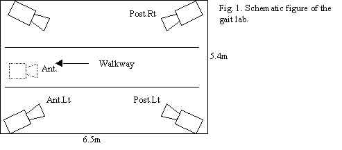 Figure 1 illustrates the camera positions.
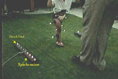
- Set two fixed point markers on each side of walkway for automatic
digitization.
- You may place synchronizing LED’s on each side of walkway, if
desired. Any synchronization method can be used. You may Genlock the cameras,
or use lights or any event that can be seen in the video to synchronize the cameras. The
APASgait make synchronization very simple by allowing variety of methods of doing it.
- Set control frame on the walkway and record the camcorders only for a
moment – more than 0.033 second would be enough!!! You really need only one frame.
But 10 frames are o.k. to make things simple.
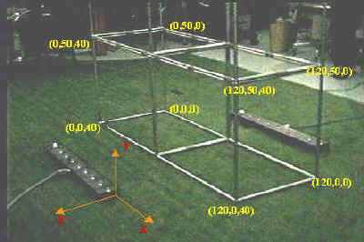
Fig. 3. Control frame for the children
- Movement Recording:
Aim: Record the movement
(gait) of the patient.
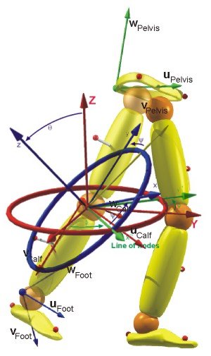
Comment: To digitize automatically and to calculate 3D angles
–the more important purpose- , you must attach a number of reflective markers on the
specific body parts of the patient. Two kind of activities are to be recorded, static and
dynamic. We use Helen Hayes(HH) marker set with some modification.
Activities:
Attach 19 markers(or 15markers as original HH marker set) on the
patient’s pelvis, both legs and both feet.
For Pelvis: right and left ASIS(Anterior Superior Iliac
Spine), midpoint between both PSIS
For right and left Thighs: a wand(stick) marker attached on the lat.
wall of thigh, a marker attached on the center of lat. Femoral Condyle. On what point
should be the third marker? You do not have to attach it. Hip joint center is calculated
from the three pelvic markers. It can be used the third marker for the thigh. Medial
condylar marker is needed only for static sequence.(not used in original HH set)
For right and left lower legs: a wand(stick) marker attached on the
lat. wall of lower leg, a marker attached on the center of lat. Malleolus. Knee joint
center in thigh can be used the third marker for the lower leg. Medial malleolus marker is
needed only for static sequence(not used in original HH set)
For right and left feet: Metatarsal head area of 2nd and 3rd
toe, Heel marker is needed only for static sequence. Let the patient stand on the midpoint
of the walkway with as little movement as possible.
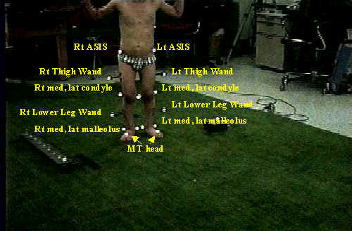
Fig. 4. Static View from Anterior Right
camcorder
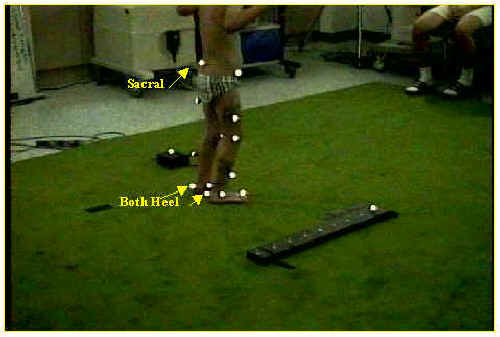
Fig. 5. Static View from Posterior Right camcorder
- Record the static sequence with all camcorders
- Let the patient stand on the starting point of the walkway .
- Detach both heel, medial malleolus and medial condyle markers. If you attach heel
markers during gait, auto-digi will be difficult because the heel markers frequently join
lat. Malleolus markers.
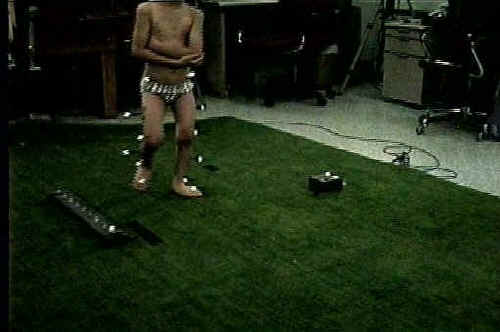
Fig.6. Dynamic(during gait) Views from Anterior Right
camcorder: the heel, medial malleolus and medial condyle markers are detached.
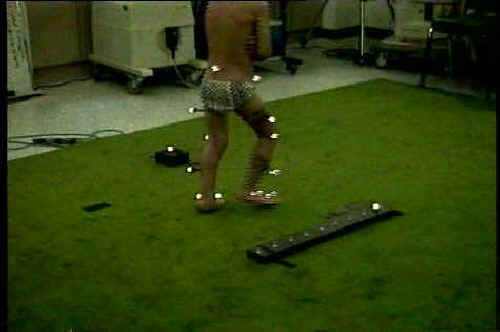
Fig.7. Dynamic (during gait) Views from Posterior Right camcorder: the heel, medial
malleolus and medial condyle markers are detached.
- Turn all camcorders record on.
- Let him walk: Walking speed can be controlled or not. Usually not controlled.
- During walking, turn on a LED of the synchronizer. One LED for one sequence of gait.
- Record off all the camcorders.
3. Post processing
Aim: Get three dimensional coordinates of each
markers of static and dynamic sequence.
Comment: Capturing, digitizing, transformation and filtering for
the static and dynamic sequence.
Activities:
- Capture and trim the recorded movement, static and dynamic on each
camcorders. For static sequence, more than 6 frames would be enough. For dynamic(gait)
sequence, one cycle(from foot-on point of one leg to the second foot-on point of the same
leg) or one and half cycle(one cycle and until the other leg steps on the ground) should
be included. We capture more than 10 frames before and after the exact duration of
movement. After capturing completed, you should have (number of camcorder)* 2 avi’s.
Align the frames of avi’s according to the synchronization point and trim them out.
- Digitize the dynamic sequence. Automatic digitization of APAS works so fine and
efficiently. We set different ‘Invisible point’ table for each view.
Fig.8. Auto-Digitizing the Post. Left view
For Post. Right view(from Post. Right camcorder)
= Rt MT, Rt Lat Malleolus, Rt Lower Leg Wand, Rt Lat
Condyle, Rt Thigh Wand, Rt ASIS, SACRAL markers are seen beautifully. So, we tick those
points as visible in invisible point table.

Fig.9.
Auto-Digitizing the Post. Right view
For Ant. Left view(from Ant. Left camcorder)
= Lt MT, Lt Lat Malleolus, Lt Lower Leg Wand, Lt Lat
Condyle, Lt Thigh Wand, Lt ASIS markers are seen beautifully. So, we tick those points as
visible in invisible point table. The ASIS markers are not seen when the patient swings
his arms. So, we usually let him flex his elbows. It may influence on his gait pattern a
little. One more camcorder in front of him will solve this problem.


Fig.11. Auto-Digitizing the Ant. Right view
- Digitize the static sequence. You can do it automatically or manually.
- Digitize control frame for each sequence
- Transform each sequence – static, dynamic.
- Filter the sequences. Digital filtering with cutoff frequency 5 or 8 would be better
than cubic spline, especially for the sequences digitized automatically. The
auto-digitized sequences have too small noise and some markers(ASIS, Sacral, …) are
moving in a small range, so, cubic spline filter would cut the signal off too much.
Please, see below two graphs. The graph A and B are about the Lt. ASIS from the same
dynamic sequence. Graph A is filtered by cubic spline with 1.ocm value. Graph B is
filtered by digital filter with 8Hz cut off. The Y and Z coordinates of ASIS show a small
range of excursion. So, the cubic spline filters too much real signal. If you want to use
cubic spline, you must input the filtering value as 0.1cm or less. But this kind of value
is not suitable for the wand markers which move in jerky manner especially when the
legs(feet) strike the ground. I think the digital filter is better.


|
 = Lt MT, Lt Lat Malleolus, Lt Lower Leg Wand, Lt
Lat Condyle, Lt Thigh Wand, Lt ASIS, SACRAL markers are seen beautifully. So, we tick
those points as visible in invisible point table.
= Lt MT, Lt Lat Malleolus, Lt Lower Leg Wand, Lt
Lat Condyle, Lt Thigh Wand, Lt ASIS, SACRAL markers are seen beautifully. So, we tick
those points as visible in invisible point table.

