Lesson 5
The Digitizing Module
Introduction
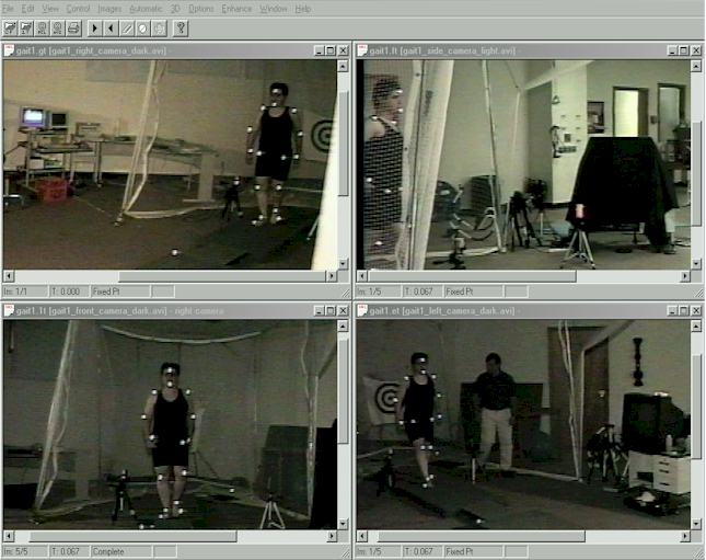
The APAS System is the only system in the world that can digitize simultaneously 4 video images and use state of the art video enhancement.
Digitizing is the first step for analysis after
the recorded images have been captured trimmed and stored on the hard disk of the
computer. By trimming the raw video files, the sequences become synchronized and the
frames are match to the same time base line. The APAS 4 Screens DIGITIZING APPLICATION
(DIGI4) software is a Windows 95/98/NT based program for digitizing images to be analyzed
using the Ariel Performance Analysis System (APAS).
Initially, the
video image is captured and stored in memory. This eliminates any further need for video
apparatus. The image sequence is then retrieved from computer memory and displayed,
on the digitizing monitor. The two video files that we will be use in this tutorials are:
1. gait1_right_camera_trimmed.AVI (1MB) Trimmed file for the right camera
2. gait1_left_camera_trimmed.AVI (1MB) Trimmed file for the left camera
Make sure that you download these files so you can digitize them.
The captured image can be enhanced or altered in several ways. These included Zooming the whole frame or a defined, isolated portion of the view. Changing the size may help the person digitizing to more accurately determine a particular joint which in the standard view could not be identified. This is a very unique feature which allow small images to be enlarged and digitized. A dynamic zoomed window, in addition to the regular zoom, allow very accurate determination of the body's joint center or the location of a marker. The following video file demonstrate some of these functions. (2.5 MB). (Click here to see or download the video file:video/zooming_and_enhancement0001.avi 2.5MB). You may download the file and play it with the media player or, if you have a fast internet line, you may open it in real time. This video file illustrates only few functions which I am sure will impress you. All functions will be demonstrated in latter lessons and a very detail explanation will be given.
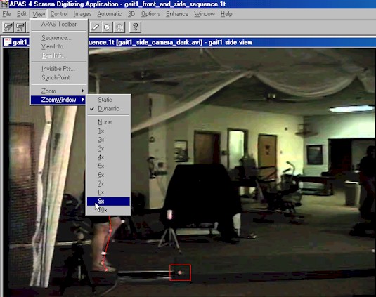
You can select from x1 to x10 dynamic zoomed window.
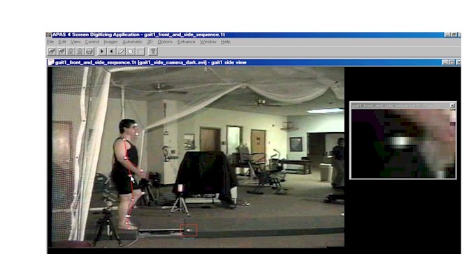
Dynamic Zoomed Window is one of the uniqness of the
APAS, where you can point to any location
on the video image and a dyanamic zoomed window will be open and show the location in
magnification OF
x1 TO x10. This window is dynamically moves with the cursor
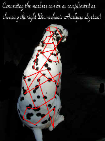
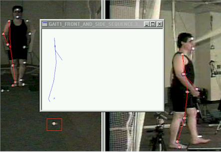
Using the video cursor, the location of each of the subject's body joints or marker, is selected and entered into the computer. As each point is selected, it is displayed within the video image on the monitor. This assists the user to evaluate his current joint selection with the perspective of the previously identified joint center. Another useful feature is the "rubber-band" effect. This situation occurs when the previously selected joint in the current frame is "fixed" while the next joint center is being located. The computer connects the preceding joint center with the cursor. As the cursor is moved to establish the joint center location, a line is created which moves according to the cursor motion. This assist in digitizing since the connection between the two points represents the segment between the two joints.
"Rubber-band" assistance
The following video clip show step by step the slection and the use of the dynamic zoomed window. Download the file .avi and use the MS Media Player to advance the video frame by frame to see the functions. This video was highly compressed to save download time. Also, only few frames per second were captured with the APAS system to allow efficient demonstration and in the same time to save the download time. Digitizing Zoomed function video. (1.5MB)
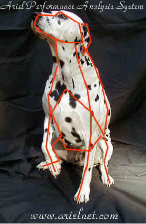
One may ask: "why do I need a video? there are systems that digitize the markers for me and I do not need the video....." Well, my answer to this is that without the picture you missed the performance. You have analyzed markers, but not human. Location of markers changing with skin movement. Different position of the body's segment may give different coordinates. You must have the video to demonstrate and analyze the results. You cannot have eyes and act like a blind. You must see the original video to make valid and reliable decision about the activity. In addition, by having the video, you always maintain the original data. If in the future you need to re-digitize the raw data since you decided to add a point location, you can always go back to the original video. With markers, you lost the original performance.
For more information please read the following detail dissertation about markers:
Three-Dimensional
Tibiocalcaneal and Tibiofemoral Kinematics During Human Locomotion - Measured with
External and Bone Markers
by Christoph Reinschmidt
After reading this Dissertation, you will find out, that there are many ways to determine a potential joint center. But in all cases there are significant errors. Even by inserting marker to the bone itself, which is not practical, yield level of error. From my experience over 30 years using many of the methods, I did not find yet a better method then using knowledge of anatomy and manually estimate where the joint is utilizing the great power of the brain and the visual cortex, to determine with your eyes where the estimated joint is. Unfortunately, this take longer time to achieve since you need to digitize manually each point. This why we developed the automatic method which utilize filters and enhancement to locate the joint automatically. However, again, this associate with some level of error. What is important is that you can evaluate the error by looking at the points after they the digitizing process was finished. To do this we allow you to super imposed the "stick figures" over the original video for verification and checking. Then if a point is our of line, you can manually correct it.
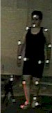
Digitizing can be performed in one of two modes, either Manual or Automatic. Manual digitizing is performed under computer control and the digitizing of video images is computer assisted. Under manual control, user participation in the digitizing process provides an opportunity for error checking and visual feedback which rarely slows the digitizing process adversely. A trained operator with a reasonable knowledge of anatomy and a consistent pattern of digitizing can rapidly produce high-quality digitized images. Automatic digitizing requires some sort of visible markers. These may be reflective markers, LED's or simply markers with a high contrast to the immediate background such as white markers against dark background or black markers against a white background. User input is minimal as the computer automatically tracks the markers based on color, contrast, position, velocity and acceleration.
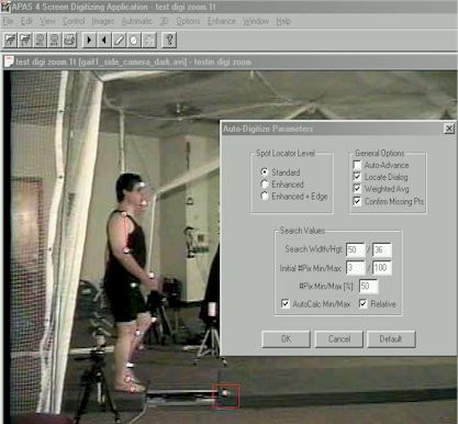
Global Parameters selection for Automatic Digitizing (Discussed in detail latter).
Full 3-Dimensional
integration has also been incorporated. During the digitizing process, 3D stick figures
and graphical information can be displayed simultaneously. Graphs and stick figure images
are updated immediately as the sequence is digitized.
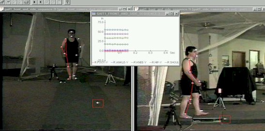
Real Time calculations of 3D parameters while automatic or manual digitizing
Real Time Stick Figure orientation in x,y or z configuration
As one can see, the APAS system is very powerful
in many ways. While you digitize automatically, you can observe the orthogonal stick
figures or the raw data displacement in x,y, and z coordinates. This allow to see
the accuracy of the system while it is processing and if anything is not acceptable, to
halt the progress and correct it. One of the most amazing thing about the APAS system is
that you always see the video data. The APAS system is the only system in the World that
can do it. With other systems the digitized point could fall out of the body's joint and
you will never know about it, especially where all other systems filter the raw data, so
the user will not find these errors latter. With the APAS system you always maintain the
raw data. An absolute requirement for valid experimental procedures. This is one of the
reason why the APAS system came
at the top in the official comparison of existing systems.
The APAS system
was designed from the ground up to the Internet standards. Ariel Dynamics was one of the
first in this technology, to utilize the Internet for files and data interchange. We used
the Internet as early as 1976, but, at that time it was actually a Unix system and we ran
mostly FTP protocols. In 1992, Ariel Dynamics used Mosaic I from the University of
Illinois, and we were one of the first
100 organizations in the World to use a browser. In 1995, I presented a paper at
the ISB indicating the Internet as the future for any science in the World. At that
meeting I demonstrated digitizing through the net between different sites. We were
the first on the Internet for any Biomchanics organization and we designed our system
accordingly. Today, the APAS system is still the only Internet compatible system in
the World. The file structure of the APAS also opens the possibility of sharing data with
other users. Since data records are stored as a file on the hard disk, these files can be
transmitted worldwide by modem or through File Transfer Protocols (FTP) on the Internet
for collaborative purposes. Files can be downloaded from the web pages and collaborative
work can be done with people around the World simultaneously. In a University environment,
all files can be maintain on a main server and people around the World can share the data
and results through the Internet and Intranet.
The DIGI4 program presents many
options and features to the user, however, they are relatively easy to master once you
understand the concepts behind them. This Tutorial is arranged to teach you these concepts
in a logical order by showing you in a step-by-step fashion, how to use DIGI4.
In Summary, Some of the essential features in the Digitizing Module are as follows:
- Multiple Screen Digitizing. Up to four images can be displayed and digitized simultaneously.
- Multimedia Compatible Image files can be displayed in *.AVI format utilizing Intel Indeo technology and others.
- Real-Time Video Capture. Video can be captured directly from the video source at rates up to 1000 fields per second, depending on the type of camera.
- Real-Time 3D Transformation. 3D data files can be generated and displayed simultaneously with the digitizing process.
- Software Support For Panning Camera. Software developed by Ariel Dynamics allows for "Panning" cameras without additional hardware.
SYSTEM REQUIREMENTS
The
following table provides the basic guidelines for required hardware to provide the best
possible performance. Required software includes Microsoft Windows 95 or later and Ariel
Revision 3.5 or later.
Image Format Required Hardware:
*.PCL(*.PCX) No Additional Hardware Required
*.AVI Video For Windows Compliant Video Board
The Digitizing Process
To start the Digitizing Module,
Double-click the DIGI4 icon ![]() located in the APAS window group. The
main DIGITIZE menu will appear. You are now ready to create a new digitizing Sequence or
restore a previously created Sequence.
located in the APAS window group. The
main DIGITIZE menu will appear. You are now ready to create a new digitizing Sequence or
restore a previously created Sequence.
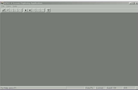
Digitizing Screen 1
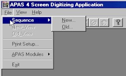
Selection of new or old sequence
The following video file (2MB) illustrates the procedures in creating a new sequence and a viewing in the Digitizing Module. A sequence contain multiple views. Each camera create a view. A sequence can have up to 256 views or 256 cameras. Of course, this is not necessary and in most cases only 2 to 5 views or cameras are used. Make sure that you download this video file and follow it step by step with the MS Media Player. You will see the process of selecting a new sequence and a new view.
SCREEN LAYOUT
Prior to beginning the Digitizing process, you should familiarize yourself with the screen layouts of the various digitizing menus. Many functions can be selected using the DIGI4 Tool Bar or by selecting the appropriate command from the Pull-Down Menus.
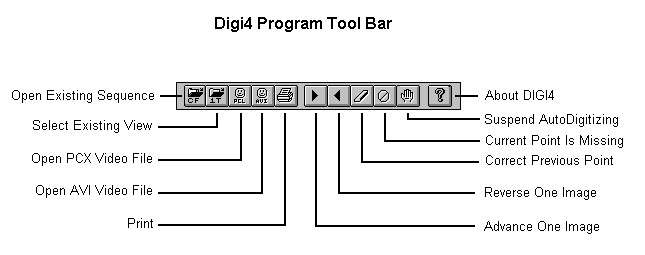
THE DIGI4 TOOL BAR
You can activate many functions by selecting the icons located on the DIGI4 program tool bar. The tool bar is located near the top of the window. Icons are pictorial representations of commands or functions. You can access the following commands by clicking the appropriate icon.
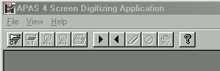
The Digitizing Module Tool Bar
THE STATUS BAR
The status bar provides useful information about the current status of the image file. The status bar is located at the bottom of the DIGI4 window. The far left side of the status bar is divided into five separate fields; Sequence Name Field, Control/Data Point Field, Frame Lock Status Field, AutoDigitizing Status Field and the Current X/Y Position Field.
![]()
Sequence
Name indicates the name of the current sequence. A missing sequence name indicates that
the sequence has not been selected.
Control/Data Points indicates
whether the current display shows sequence data points or the control frame.
Image Lock Status indicates the
current state of the Image Lock as specified in the Lock command of the Images menu. When
images are locked, the advance/reverse command acts on all open view windows. If the
images are unlocked, the advance/reverse command affects only the active window.
AutoDigitizing Status indicates
the current status of the AutoDigitizing option. When AutoDigitizing is active, the first
frames will display AutoD : LEARN. Afterwards, the AutoD : ON indicator will be visible.
When AutoDigitizing in not active the AutoD : OFF will be displayed.
X/Y Cursor Position indicates the current X and Y cursor position on the color display.
VIEW WINDOW LAYOUT
When
a View Window is opened, additional windows will be displayed inside the DIGI4 main
window. Up to four windows can be opened simultaneously. The View Title will be displayed
at the top of each View Window. The View Window title incorporates the *.1t filename along
with the IMAGE file being used and the View information string. The View Window Status bar
is divided into four fields and is located at the bottom of each View Window. The first
field displays the digitized Image number and the current Image number of the file. For
example, the Image # designated as 100/150 would mean that there are 150 images up to the
currently displayed image while only 100 of the 150 images have been digitized. You do not
have to digitize every image. The program will keep track of the timing when you skip
frames. The second field displays the current sequence Time. This number is calculated
based on the FRAME RATE value specified in the View Information menu. If a frame rate of
60 is used, each time the image is advanced the Time field will be incremented by a value
of 1/60 = 0.01667 seconds. (1/50 for PAL). The Next Point field specifies which point
should be digitized next for this window. The order of the points is determined by the
Point Identification Table. When all points have been digitized for the current image this
field will display the label COMPLETE. The Bright/Dark field is active only when
AutoDigitizing. This field indicates whether the markers used for AutoDigitizing are
Bright (against a dark background) or Dark (against a light background). Each individual
view can be independently set for Bright or Dark markers.
Scroll Bars located immediately above the View Status bar and also at the right side of
the View Window allow the image to be scrolled left/right and up/down. The small arrow in
the upper right corner of the View Window can be used to expand the window to the full
screen.
MOUSE BUTTON FUNCTIONS
The Digitizing phase of the analysis makes extensive use of the mouse. The arrow keys can be utilized for "fine-tuning" the digitized point, however, most users rely solely on the mouse. The APAS computer is supplied with either a two or three button mouse. There is a Left (L), Middle (M) and Right (R) button. Several functions have been incorporated into the mouse buttons to simplify the Digitizing process. These functions are listed when you select the ? icon from the DIGI4 Toolbar.
Left - Selects the current position of the cursor as the digitized point location
Middle - Corrects the last digitized point. When a joint is Digitized incorrectly, the Middle mouse button can be used to correct the point. The cursor will reverse one joint for each time the Middle button is pressed. Of course, in the Automatic Mode you do not use the mouse buttons.
Right - Moves cursor to the "estimated" location of the next point to be digitized. Since this requires previous information to "estimate" the point location, this function has no affect in the first frame
Ctrl-Left [Drag & Drop] - Press the Control key and Left mouse button simultaneously to Drag the point nearest to cursor to desired screen location then release the mouse button. If you desire to Abort the Drag/Drop feature, simply drag off the client area and release the mouse button.
Shift-Left [ Redigitize] - Pressing the Shift key and Left mouse button simultaneously will cause a Dialog Box to appear selecting a joint. After a joint is selected, if AutoDigitizing is active, the program will perform an Initial Locate for the spot associated with the specified joint starting at the cursor location of the mouse click. If AutoDigitizing is inactive, then the specified joint is re-digitized at the cursor location of the click.
Double-Click Right - . When all the points for the current frame have been digitized and the Status Bar indicates that the image is Complete, the Right mouse button can be "double-clicked" to advance to the next image.
The following video file demonstrate the various mouse buttons. (2.5 MB) Please download the file and follow it with the MS Media Player, frame at the time while you practice the mouse clicks.
ACTIVE HOT-KEYS FOR DIGITIZING
Even though the Digitizing phase of the analysis makes extensive use of the mouse, some users may prefer to use the keyboard for several of the more common commands. The arrow keys can be utilized for "fine-tuning" the digitized point. Pressing the ENTER key is identical to the Left mouse button and will enter the cursor location as the digitized point. Several other common commands are listed below:
Key Function
DEL
Correct Previous Poing
CTL-DEL
Erase all points in Frame
ESC
Set current PT to missing
ALT-LEFT
Backup one Image
ALT-RIGHT
Advance to next Image
ALT-0
Zoom .5X
ALT-1
Zoom 1X
ALT-2
Zoom 2X
ALT-3
Zoom 3X
ALT-4
Zoom 4X
Mouse Action
Left Button
Digitize
CTL+L-Button
Drag Point
Shift+L-Button
Relocate Specific Point
CTL+Shift+Left Button Auto Locate Current Point
Right Button
Return Cursor to expected Location
Right DBL Click
Advance to Next Field
Middle Button
Delete/Correct last point
ALT-Right Arrow - When all the points for the current frame have been digitized and the Status Bar indicates that the image is Complete, pressing the ALT key and the Right Arrow key will advance to the next image.
ALT-Left Arrow - When all the points for the current frame have been digitized and the Status Bar indicates that the image is Complete, pressing the ALT key and the Left Arrow key will reverse to the previous image.
DEL - Pressing the DEL key will erase the digitized location for the current point.
[Go to Lesson 4] [Go to Lesson 6] [Go to Tutorials] [Go to Home Page]