Lesson 6
Hands-on experience with the Digitizing Module
The APAS modules have
been placed in a separate program group named APAS. On some systems there are two APAS
groups : APAS1 and APAS2. These names designate the one (color) and two monitor (mono and
color) systems respectively.
1. Double-click the DIGI4 icon located in the APAS window group. The main DIGITIZE menu
will appear. You are now ready to create a new digitizing Sequence or restore a previously
created Sequence.
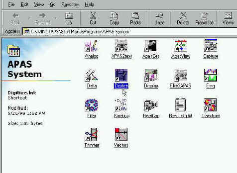
Click on the Digitizing Icon at the APAS desktop
MJPEG IMAGE ORDER
A standard video picture is made up of odd and even lines across the screen. Television standards require these lines to be interlaced. This means only half of the lines are displayed in one field. The first (odd) set of lines is displayed in the first field while the second (even) set of lines is displayed in the second field. These two fields comprise a frame, which is a complete picture.
When capturing a video sequence utilizing the full speed provided with today's video standards, it is normally required to use special VCR equipment with field-by-field stepping capabilities. Industry standard hardware and APAS software modules make it possible to capture video sequences from a VCR or camcorder directly to the computer hard drive without special requirement of expensive VCR equipment. Any VCR can be used as a video source with the APAS.
The APAS system uses hardware and software that has Motion JPEG image hardware compression that also complies with the major hardware vendors. After capturing the video to the hard drive, the APAS system allows separation of each frame to its two component fields. The APAS system is the only one in the World that can do that and create a field by field at 60 hz frame rate.
Depending on the hardware and software combinations used for recording and displaying the AVI files, it is possible for the order of the displayed fields to be reversed. This is the inherent characteristics of the capture card to show the Odd or the Even as the first field. For a normal video display, it does not make difference. You could not observe the difference since the frame is interlaced and it does not make difference which field coming first. However, for digitizing it is very critical that the first field will be the earlier one. It is also possible for the same AVI file to play in normal order on one computer and in reverse order on another computer! This is because two different capture cards from the same manufacturer may produce different fields order for some reason. For this reason, the Ariel CAPTURE, TRIM and DIGITIZE programs provides the option to specify the order for displaying the images of the AVI files.
If it appears that the images are "jerky" or are being displayed in a "zigzag" manner, the field order probably needs to be reversed. The field order is specified using the following steps. This step control can be achieved in the Capture, Trim, and Digitized module. However, it has to be done only in one of them and the order will maintain itself for the future since this order is designated in the Windows Registry and will stay there for future analysis. This why this process has to be done only once and only if by chance the video source create a reverse fields. When you are doing it once with any of the following modules, it will remain this way for ever for this specific computer and capture card.
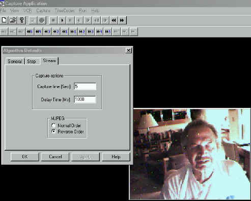
CAPTURE PROGRAM
- Select CAPTURE and CAPTURE PARAMETERS. The Algorithm Defaults menu will be displayed. Click on the STREAM tab to display the Streaming Capture options menu. Select either Normal or Reverse order in the MJPEG section. The current selection is indicated by the black dot to the left of the option. NOTE: When this option is changed, it affects all other APAS software modules where the AVI file can be displayed (Capture, Trim, Digitize, Display, Vectors etc.)
- Select OK to proceed or CANCEL to abort.
Slection of Normal and Reverse fields order
TRIM PROGRAM
- Select OPTIONS and MJPEG. The MJPEG Options menu will be displayed. Left-click either Normal or Reverse order. The current selection is indicated by the black dot to the left of the option. NOTE: When this option is changed, it affects all other APAS software modules where the AVI file can be displayed (Capture, Digitize, Display, Vectors etc.)
- Select OK to proceed or CANCEL to abort.
Selecting the proper order fields from the Trim Module
As one can see there is a choice between "Normal Order" and "Reverse Order". In most of the cases the Normal Order, which the Odd field is first, will be in effect and you do not need to make any adjustment. However, some capture cards like to capture the Even field first and then the video when it is advance field by field will look as the person walking forward and backward between fields. In this case, you must select the Reverse Order option. When you are doing it once, it does not change on this computer since the capture card is the same for that specific computer.
DIGITIZE PROGRAM
- Select FILE, SEQUENCE and NEW (or OLD) and specify the Sequence Name.
- Select FILE, NEW (or OLD) VIEW and specify the View File and the corresponding AVI file.
- Select IMAGES and VIDEO to display the Video Options menu. Left-click either Normal or Reverse order. The current selection is indicated by the black dot to the left of the option. NOTE: When this option is changed, it affects all other APAS software modules where the AVI file can be displayed (Capture, Trim, Digitize, Display, Vectors etc.)
- Select OK to proceed or CANCEL to abort.
The two steps are shown as follows:
Selection of the Images and then Video
After selecting the Video the option is given
To demonstrate this phenomenon you can download or open the following video fiels. They are only approximately 400K.
To see the video
file in the wrong order click on the following file: Field_order_1.avi (400K)![]()
To see the video file in the proper order
click on the following file: Field_order_2.avi
(400K)![]()
When you observe the "Field Order 1.avi" file you can see the movement between fields. The subject move forward and then backward one field at the time. The reason is that the Even field rather then the Odd field are first in the sequence. In the file "Field order 2.avi", the Odd field is first and the order is correct.
Just remember, in most cases the orders are correct. But some capture card reverse the order for some reason. Since these capture cards were not designed for Biomechanical purposes, the manufacturer did not care for the order of the fields. In our case it is very critical that it is done correctly and therefore we wrote elaborate software to be able to reverse the field. Normally, this would be impossible.
The following video file Field_order3.avi (1.8MB) illustrates how to access the Field Order mode from the various modules. As was said before, you need to decide about the order only one time and only from one of these modules. After you selected the proper order you should never worry about it again. You can download all the files to particular directory and then open them with the Microsoft Media Player older version program. This will allow you to advance the pictures one at the time and control the video for better observation. You can find the Mplayer.exe file in your Windows directory. (c:\windows\Mplayer.exe).
WINDOWS WIN.INI FILE
The Image Order information is stored in the WIN.INI file. Once this parameter is set in the Capture, Trim, or Digitize module, the Ariel software will remember the current setting. The following information is listed in the WIN.INI file of the APAS computer.
[APAS System Information]
ReverseFields=0
NtscPal=0
When Reverse Fields is set to 0, the APAS software reads the video fields in normal order. (Odd field first). When the Reverse Fields is set to 1, the video fields are displayed in reverse order. (Even Field first).
![]()
CREATING A NEW SEQUENCE FILE
It is essential to have a good video file. The markers must have a good contrast and the background must be "clean". The computer algorithm must determine the center of the marker. For that, many calculations are made to be able to run the image processing to come with a solution. The following E-mails messages are an answers to one of our customer who, obviously, did not prepare the "background" and the "foreground" for the video correctly:
![]()
This is a response from:
Erik B. Simonsen, Associate Professor, M.Sc. Ph.D.
Institute of Medical Anatomy section C.
Panum Institute. University of Copenhagen
Blegdamsvej 3., DK-2200 Copenhagen N
DENMARK
Hi Daren,
My name is Erik B. Simonsen. I have a gaitlab, in which we use the APAS
system with 5 cameras and two forceplates. I may be able to help you a bit.
I will try to answer your questions between the lines:
>
>Hi -
>
>Captured video with four cameras on Friday, and have been using esp. the
Trim, Digi4, and Transform programs. My biggest questions have come from
using Digi4:
>
>1) Can I turn the bell off during Auto Digitize? Even when Auto Digitize
works it's running quite slow and I'm wondering if things would speed up
without the bell, or if there is any other way to speed up the process.
It seems something is wrong with your PC. Automaticmatic digitizing is
normally not a slow process. If you choose AUTOADVANCE and provided the
markers can be found automatically it should take less than 5 seconds for
100 frames.
>
>2) Auto digitize is failing to recognize point markers when there is motion
blur due to movement during the frame... and it doesn't take as much
movement as I'd expected to cause a problem. Even just some fairly brisk
walking seemed enough to do it. Any way to make it work or is manual
digitizing required here? (I can send you some sample images if you'd like
to see what I'm talking about BTW).
You should always use a shutter on the camera. For walking I use a rather
long shutter: 1/250 s
>
>3) I always get an error upon opening the AVI file for a View which says:
"Video Image Info does not match Tracefile Filmspeed". What does this
mean?
I dont know the reason. I always ignore it.
>
>4) I did a capture where I was walking in a circle around the center of my
capture area. As I turned relative to a camera's view that would mean of
course that different markers would disappear and appear to that camera. To
handle this do I simply have to mark the markers visible at the beginning
frame, let the auto digitize run until new markers appear/disappear as I
turn or change position, then stop the auto digitize and restart it again
where I mark the newly visible markers during it's "learning" frame? (this
is what I did - my *real* question is if there is a faster way :)
Well, the most difficult situation you can imagine is what you describe:
walking on a circle or doing a twisting sommersault.
I wont recommend that you let the auto digitize run, you should always
advance each frame your self. In this way you can avoid mixing of markers
and other errors. Only if I have a very simple marker setup, where I know
nothing can go wrong, I let it run by it self.
For each camera view you should tell the system, which markers are
invisible, but you have to make sure that each marker will always be visible
for at least two cameras. Actually, it is best to make a strategy for this.
If a marker becomes invisible temporarily it is better to guess where it is
rather than digitize it as "missing" by the ESC key or define it as
invisible. As you suggest is possible to turn a marker on and off as visible
or invisible during the whole process, but often it is much better to guess.
The system does not look for an invisible marker to become visible again.
>
>5) Should I expect to have the above issue from markers being occluded by
the subject's body? For example during my walk cycle the left camera's view
would intermittently see the right hip, knee, ankle, foot, etc. as the legs
scissor back and forth with the walk cycle. So my question is should I have
to manually mark the right side markers each time they reappear from having
been occluded by the left side of the body? Or is auto-digitize smart
enough that it should be able to reaquire these markers when they reappear?
(it didn't appear to me that it was in my little test)
Please see my comments above.
>
>6) Should I be concerned about markers like the above not being labeled?
i.e. my goal is to generate 3D data, and you say you need two cameras to see
a marker to get the 3D coordinate, so maybe I shouldn't care that the left
camera view doesn't have the right side markers identified? (i.e. since I
know the right camera view and front camera views will see them?)
I use 5 cameras for walking, two from a side view and one from a frontal
view. The two cameras from e.g. the left side are never expected to see the
markers on the right side of the body. Furthermore, it is my impression that
accuracy does not suffer from using only two instead of three cameras to see
a marker.
>
>7) If auto-digitizing misses a marker (e.g. due to the "motion
blurring"
problem) is there an easy way to manually identify that single marker, i.e.
*without* having to *unlabel* all the subsequent markers with the "correct"
function? Ideally I would like to use the auto-advance feature to batch
process the whole sequence (e.g. over lunch), then go back and review the
results and correct these problem markers.
You just correct any mistakes on every frame during the process. This is why
you should also establish good contrast in your recordings. I have painted
the floor and walls dark to enhance contrast and often we dress the subjects
in a tight blach suit with white markers. With five cameras we never through
light on the subject, we rather dirict light to the ceiling.
>
>8) The real concern behind most of my above questions is that it looks to
me from my limited test example that there is a *lot* more manual digitizing
required than I had hoped for to generate a motion capture file. You had
told me last week that you are working on supporting different colored
markers in a future release of APAS... so now I'm wondering if these
colored markers will actually be used to enhance the auto-digitizer to
auto-identify the markers based on color? My gut feeling right now is that
if that's the case that feature might make the difference for my uses (where
I am doing computer animation, not gait analysis) between APAS being a once
in a blue moon tool for very short captures and it being a really valuable
daily use tool.
We digitize about 80 frames from 5 cameras (a total of 400 frames) in less
than 60 minutes by a semiautomatic approach AND then the digitizing is over
and done and error free, which is seldom the case for online systems.
Darren, I hope this information helps, otherwise send me an email.
>
>Thanks again,
>
>Darren Cruse
>www.anet-stl.com/~dcruse
>Freak Accident Digital Media
![]()
This response is from Dr. Jeremy Wise:
Hello Darren-
Captured video with four cameras on Friday, and have been using esp. the Trim, Digi4, and Transform programs. My biggest questions have come from using Digi4:
1) Can I turn the bell off during Auto Digitize? Even when Auto Digitize works it's running quite slow and I'm wondering if things would speed up without the bell, or if there is any other way to speed up the process.
>>
The bell cannot be turned off at the moment but that would not cause the program to run slowly. The one think that will most directly impact the time for locating the markers is the size of the search window specified for the markers. When the search window is large there are multiple candidates per joint and many combinations which must be checked. You want a search area large enough that the frame to frame motion will result in the marker lying inside the search rectangle centered on the expected location of the point and not unnecessarily large. Usually a 50x50 rectangle works.
>>
2) Auto digitize is failing to recognize point markers when there is motion blur due to movement during the frame... and it doesn't take as much movement as I'd expected to cause a problem. Even just some fairly brisk walking seemed enough to do it. Any way to make it work or is manual digitizing required here? (I can send you some sample images if you'd like to see what I'm talking about BTW).
>>
The blurring is a result of recording with an unshuttered camera. The software has loose requirements regarding size, shape & brightness and it appears that those requirements are being exceeded. The use of an unshuttered camera not only results in a blurred, elongated image but also the time for the image is not known. Use of an unshuttered camera with APAS is not recommended & I cannot help you with this.
>>
3) I always get an error upon opening the AVI file for a View which says: "Video Image Info does not match Tracefile Filmspeed". What does this mean?
>>
When a sequence of video is saved to an AVI file an image rate is saved in the AVI file. For example, if you capture NTSC at full rate the image speed stored in the file is 60 hz. When that same file is opened with Digi4 one can specify a skip factor giving possible image rates of 60, 30, 20, 15, etc Hz. When a new "View" is created in Digi4 one specifies the rate for the view which specifies the time between consecutive images in the traced file. The message is alerting you to the fact that the AVI rate modified by the skip factor does not match the "View" rate. This message is a warning only. The "View" rate always overrides the rate from the AVI.
>>
4) I did a capture where I was walking in a circle around the center of my capture area. As I turned relative to a camera's view that would mean of course that different markers would disappear and appear to that camera. To handle this do I simply have to mark the markers visible at the beginning frame, let the auto digitize run until new markers appear/disappear as I turn or change position, then stop the auto digitize and restart it again where I mark the newly visible markers during it's "learning" frame? (this is what I did - my *real* question is if there is a faster way :)
>>
Typically, for a given camera, a particular marker is either visible or not for a number of consecutive frames. When a marker leaves the field of view for a camera, I would mark it as " Invisible" and when it returns mark it as "Visible". It should not be necessary to stop & restart auto-digitizing to go thru the learning phase. When a marker appears for which there has been no learning the program will request the operator to manually digitize the point. If you hold down the SHIFT+CONTROL keys while digitizing this will force the program to go through the "Learning phase" for the point. You can do this whenever the program does not locate a point the you think it should have.
>>
5) Should I expect to have the above issue from markers being occluded by the subject's body? For example during my walk cycle the left camera's view would intermittently see the right hip, knee, ankle, foot, etc. as the legs scissor back and forth with the walk cycle. So my question is should I have to manually mark the right side markers each time they reappear from having been occluded by the left side of the body? Or is auto-digitize smart enough that it should be able to reaquire these markers when they reappear? (it didn't appear to me that it was in my little test)
>>
When a marker temporarily cannot be seen it should be flagged as "MISSING". This can be done by pressing the "Esc" key or by clicking on the icon for "Missing". It will be smart enough if the marker re-appears within the search rectangle centered about the expected location of the point.
>>
6) Should I be concerned about markers like the above not being labeled? i.e. my goal is to generate 3D data, and you say you need two cameras to see a marker to get the 3D coordinate, so maybe I shouldn't care that the left camera view doesn't have the right side markers identified? (i.e. since I know the right camera view and front camera views will see them?)
>>
This is correct, as long as 2 or more cameras cann "see" a marker 3D can be calculated with mre being better. It has been our experience that one needs 6 cameras to compeletely cover a 360 degree twist. When using changing sets of cameras which see a point it is particularly critical to have very accurate calibration data. Otherwise small jumps in the data will appear when a different set of camera sees a point.
>>
7) If auto-digitizing misses a marker (e.g. due to the "motion blurring" problem) is there an easy way to manually identify that single marker, i.e. *without* having to *unlabel* all the subsequent markers with the "correct" function? Ideally I would like to use the auto-advance feature to batch process the whole sequence (e.g. over lunch), then go back and review the results and correct these problem markers.
>>
Under Automatic/GlobalOptions there is a checkbox for "Confirm missing pts". If you check this box, the program will pause at the missing point and require you to manually digitize the point.
>>
8) The real concern behind most of my above questions is that it looks to me from my limited test example that there is a *lot* more manual digitizing required than I had hoped for to generate a motion capture file. You had told me last week that you are working on supporting different colored markers in a future release of APAS... so now I'm wondering if these colored markers will actually be used to enhance the auto-digitizer to auto-identify the markers based on color? My gut feeling right now is that if that's the case that feature might make the difference for my uses (where I am doing computer animation, not gait analysis) between APAS being a once in a blue moon tool for very short captures and it being a really valuable daily use tool.
>>
It sounds to me like your automatic digitizing was not properly "tuned"
. Hopefully it will perform more to your satisfaction after you have implemented some of the suggestions I have made above. However, one cannot expect the system to find markers which are missing, obscured or blurred. If you would send me a shork clip of your video data I will take a look at it. Can you also tell me what version of the APAS software you are running.>>
![]()
1. Choose the SEQUENCE, NEW command from the FILE menu. The NEW File Dialog box will appear.
Selecting "File; Sequence; New"
2. Specify the Name
and location of the New Sequence file.
The NEW File Dialog box looks for APAS sequence file types (files that
have the extension of .CF). The current file type is listed in the lower left corner of
the dialog box. The New File Dialog box can be used to specify the Drive, Directory, Type
and Name of the image file to be saved. Type the Name of the New image file in the File
Name box and select OK to proceed. You must have the .CF extension on the new sequence
file. What is great about the APAS is that you can have the file in anywhere on the
network. You can have it on another computer or another location around the World as long
as you have a server connected to it. This allow workgroups to work together in any
place on the Planet.
3. Enter the
Sequence Parameters
Title - The Sequence Title can be up to 40 characters long and should specify information pertaining to the activity being analyzed. Titles should be used that will enable the activity to be identified many months from now.
Units - The Units field is used to specify the units for the analysis. Available choices include millimeters (mm), centimeters (cm), meters (m), kilometers (km), inches (in), feet (ft) and miles (mi). The Unit value can be changed by selecting the arrow button to the right of the entry field. Make sure that when you enter the measurement units for the Calibration Frame, the units are match. If you select Cm. make sure the Calibration Frame x,y,z, units are in Cm.
#Points - The #Points indicates how many points will be used to analyze the activity. This value does not include the fixed point. When this option is selected, the Enter Point Selections menu will be displayed.
#Control - The #Control indicates how many Control points will be used for calibrating the image space. Two dimensional analysis requires a minimum of 2 points, however, 4 or more coplanar points are recommended. Three dimensional analysis requires a minimum of 6 non-coplanar points. When this option is selected, the Enter Control Point Coordinates menu will be displayed. For 3D measurement use at least 12 points to increase accuracy. However, only 6 are required.
Type - Type is selected when you wish to set or change the type of point (body joint) or segment identifiers used for this sequence. The currently selected type is displayed in the Type field. This can be changed by selecting the arrow button to the right of the entry field. "System" is selected when you wish to use the system default point and segment identifiers for this sequence. By selecting default identifiers all names, connections and segment masses are defined and you merely select the points to be used. System identifiers are adequate for the majority of human body motion analysis that you are likely to perform. "User-Defined" is selected when you wish to define your own point and segment names, segment connections, and segment mass information. This is typically required when analyzing performance sequences that do not involve the human body (e.g. animal studies or formation analysis).
Height - The Height is the subject's height entered in the indicated units. It is an optional field and is only used by the analysis system during kinetic analysis for the determination of "standard" body segment lengths and radii of gyration.
Weight - The Weight is the subject's weight entered in the indicated units. It is an optional field and is only used by the analysis system during kinetic analysis for the determination of "standard" body segment masses and moments of inertia.
The following video file digi_demo1.avi (.5 MB),![]() illustrates the process up to here. You can open the file if you have a fast connection,
or download it and then review it with the MS Media Player to see the process step by step
to this point.
illustrates the process up to here. You can open the file if you have a fast connection,
or download it and then review it with the MS Media Player to see the process step by step
to this point.
Read - The Read option can be used to Read the Sequence Information from a previously digitized sequence. When multiple trials are being analyzed using the same Sequence Information this option can save a significant amount of time. When the Read option is selected, the Select Sequence to Copy menu will be presented. Select the name of the sequence to be copied in the File Name field. The .CF extension is required on all file names. This option will copy the entire sequence information (title, units, #points, #control, type, height and weight in addition to segment names, connections and control point locations). The necessary fields should be modified to reflect the current sequence.
This add allot of power to the
APAS system since you can create template for different activities and the only parameter
you need to change are the name, weight and sequence name. All the connections, colors an
segment parameters are read from the template file. Lets say that I would like to
digitize a gate of a subject. And lets say, that I already did such an analysis before on
another subject. The following Video file: digi_demo2.avi
![]() (.9MB), illustrates the step by step
procedures how to read previous data into the present analysis. A full digitizing
procedures will be given latter.
(.9MB), illustrates the step by step
procedures how to read previous data into the present analysis. A full digitizing
procedures will be given latter.
Connect - The connect option should be used to re-connect System-Defined points anytime that the point information is changed. When the System-Defined Point ID's are first entered, the APAS will automatically connect the points to form the body segments. For example, the software knows that the Left Foot connects to the Left Ankle and the Left Ankle connects to the Left Knee etc. This information is saved in the Sequence file. If these points or connections are changed at anytime, the saved information is updated by selecting the Connect option. NOTE: If the CONNECT button is selected, segments that do not use System-Defined points will be erased. This button does not affect User-Defined points.
4. Specify the Point
Identifications
The left side of the menu displays the previously specified number of points. The point
ID's are selected by clicking the left mouse button on the appropriate left/right label
listed on the right side of the menu box. Select OK when all points have been selected to
return to the Sequence Parameter menu.
The following video: digi_demo3.avi![]() (1.8 MB), illustrates
the Point Identifications process.
(1.8 MB), illustrates
the Point Identifications process.
5. Specify Control Point Coordinate Locations.
Type the X, Y, Z coordinate values for each control point, pressing
ENTER after each value. Values must be entered in the units of measure selected for this
sequence or incorrect results will be computed. To display additional points that could
not be displayed on the current page, select the MORE button. The READ button allows the
ability to read the control point locations from a previously digitized sequence. When all
values have been entered, check them a second time for accuracy. Corrections may be made
by pressing the ENTER key until the cursor is positioned over the desired value. When all
values have been entered correctly, select OK to accept the values and return to the
Sequence Parameter menu.
The following Video file: digi_demo4.avi ![]() (.6 MB), illustrates the Control Points input process.
You can do it manually or read the measurements from previous digitized file. This can
save you some time. If you use the same calibration points you can read these constants
from previous digitized file or from a template.
(.6 MB), illustrates the Control Points input process.
You can do it manually or read the measurements from previous digitized file. This can
save you some time. If you use the same calibration points you can read these constants
from previous digitized file or from a template.
6. Select Connect (Only If Point ID's Have
Changed)
The connect option should be used to re-connect the points anytime that the point
information is changed. When the Point ID's are first entered, the APAS will automatically
connect the points to form the body segments. For example, the software knows that the
Left Foot connects to the Left Ankle and the Left Ankle connects to the Left Knee etc.
This information is saved in the Sequence file. If these points or connections are changed
at anytime, the saved information is updated by selecting the Connect option.
7. Select OK. You are now ready to Open a New View within the
Sequence. Up to nine views can be used to analyze a single sequence, however, only four
views can be opened simultaneously.
[Go to Lesson 5] [Go to Lesson 7] [Go to Tutorials] [Go to Home Page]