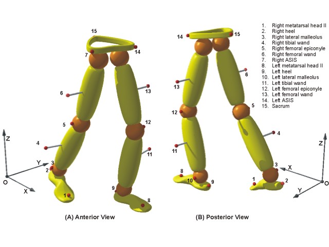
The Helen Hays Hospital Markers Set System
One of the most popular marker sets to predict the body's joints
centers from digitized data is the Helen Hays Hospital Markers Set System.
Marker Placement for Current Model:
One of the problems in capturing kinematic data is that we are
really interested in the position of the underlying skeleton, but we are only able to
measure the positions of external landmarks. Because most gait studies are two-dimensional
and concentrate on the sagittal plane, researchers have assumed that the skeletal
structure of interest lies behind the external marker. We obviously cannot do that with
our 3-D marker positions, but we can use the external landmarks to predict internal
positions. The 3-step strategy used to calculate the positions of the hip, knee, and ankle
joints on both sides of the body is as follows:
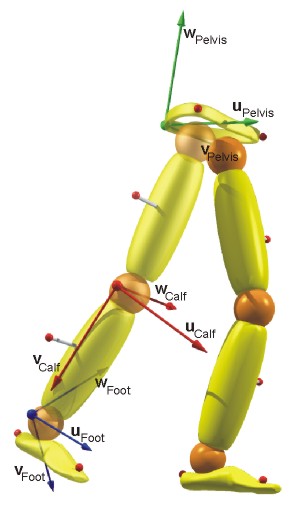
1. Select three markers for the segment of interest.
2. Create an orthogonal uvw reference system based on these three markers.
3. Use prediction equations based on anthropometric measurements and the uvw reference system to estimate the joint centre positions.
The following figures illustrate the Marker Set from
different angles:
Utilizing these marker sets on the foot allows the calculation
of the estimated joint center based on anthropometric assumptions.
After locating and defining the markers, it is important to be able
to "see" these markers with the cameras. The minimum number of cameras you can
use are 3 for these markers set. The APASgait tested results based on only 3 cameras
and produced better results than any other system. However, test conducted with 6
cameras allows detection of all the markers from at least 3 cameras throughout the
sequence. Thus, very good results can be derived relatively quickly since you do not
need to manually digitize any marker. With 3 cameras, there may be some points during
the gait cycle which necessitate manual digitization of un-seen points. This,
another advantage with video input as the raw data is that pictures are always
available for identifying the segments and the whole body allowing greater accuracy in
digitizing the markers.
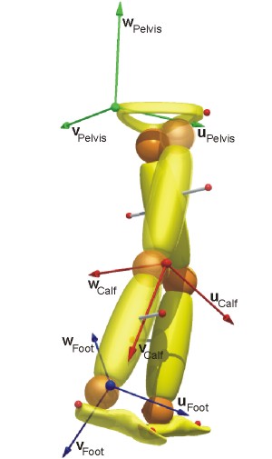
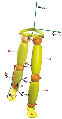
Following the digitization and transformation of the data, the
APASgait calculates the estimated joint centers of the lower extremities. The lower
extremities can perform movement in three dimensional space as shown in the following
figure:
Determining the axes of rotation about the joint center
allows calculations of other kinematic parameters such as angular and linear velocities
and acceleration. For that it is necessary to determine the Euler angles. The
equations are derived from Linear Algebra and the detail can be observe in Dr. Young-Hoo Kwon "Theoretical
Foundation". The Eulerian
Angles calculations can be found here.
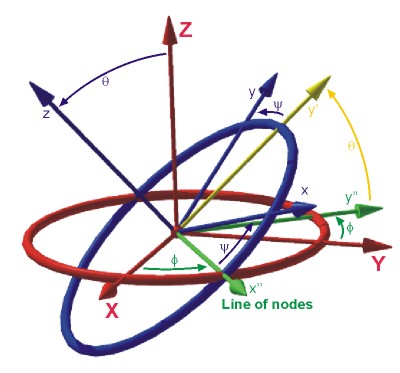
Next figure illustrates the way the Euler/Cardan angles are
determined:
If you want to learn or refresh your knowledge in 3D Kinematics,
you can go on line to the following URL:
http://www.celos.psu.edu/kinematics/
Do not be alarmed by the mathematics in
all these derivations. If your background includes Linear Algebra, these equations will be
familiar. However, there is no need to know the mathematics with the APASgait, the
same as you do not need to be a mechanical engineer to drive a Rolls Royce. You can drive
it and get to the destination elegantly. All the calculated formulas are programmed
for you to use at ease. You "drive" to your gait destination without needing to
derive the equations or design the engine.
|

